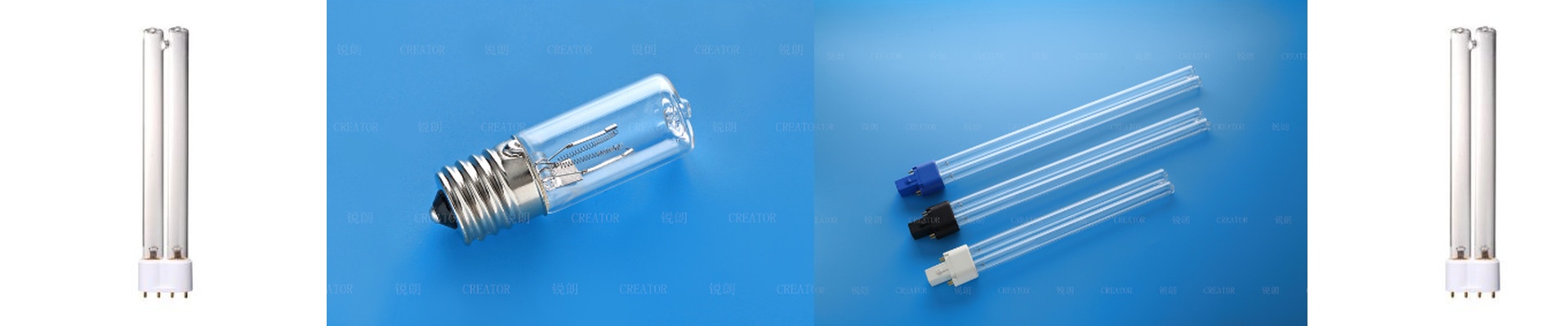
Getting the Light Right in PCB Lithography
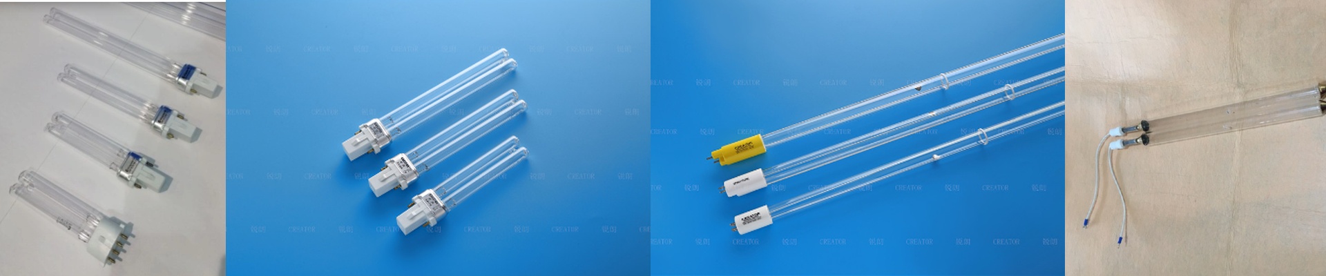
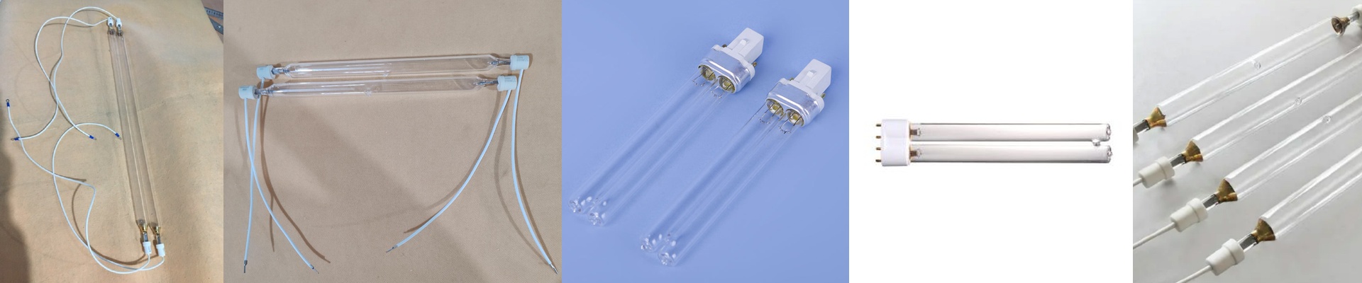
Most PCB shops get by with standard mercury vapor lamps. But when you’re dealing with high-density interconnect (HDI) boards, “standard” just doesn’t cut it. That’s where Gallium iodide (GaI) lamps come in. They hit a very specific, narrow band of UV light that matches exactly what the photoresist needs to react.
The Fight for that 0.5% Window
We spent a lot of time in R&D obsessing over a 0.5% variance in spectral energy. Why? Because in the real world, spectral drift is a nightmare. If your light shifts even a little, you start seeing “under-cured” spots or edges that are over-exposed. Suddenly, your circuit trace widths are all over the place. To stop that, we played around with the gallium iodide fill pressure and used a higher grade of pure quartz for the envelope. Now, the UV output stays locked right where it needs to be.
The Heat Struggle
Here’s the catch: high spectral density generates a ton of heat. To keep that 0.5% precision, the lamp has to stay at a very specific internal temperature. If your cooling system can’t keep up with the heat flux, the spectral peak shifts. And when that happens, your yield drops. You’ll also want a rock-solid power supply. Any little flicker or voltage ripple shows up immediately in the photon output. It’s picky, but it’s worth it.
Putting it to Work on the Floor
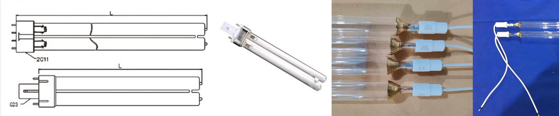
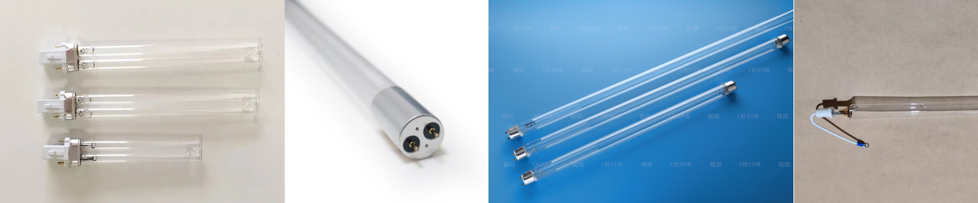
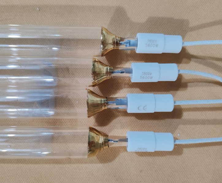
We made these a drop-in replacement, so they should fit right into most standard UV exposure frames without a fuss. One tip: make sure your connectors are seated tight. If you get oxidation at the contact point, it creates localized heat that can actually crack the quartz seal. We also used high-purity synthetic quartz to stop “solarization”—that annoying clouding that happens to glass over time. It means you aren’t swapping out lamps nearly as often. At the end of the day, tighter spectral control means fewer headaches when the boards hit the AOI (Automated Optical Inspection) stage. It really comes down to the physics of the light, not just cranking up the wattage.